Research Paper — Host anisotropy controls phosphorescent emitter orientation and OLED outcoupling
Summary
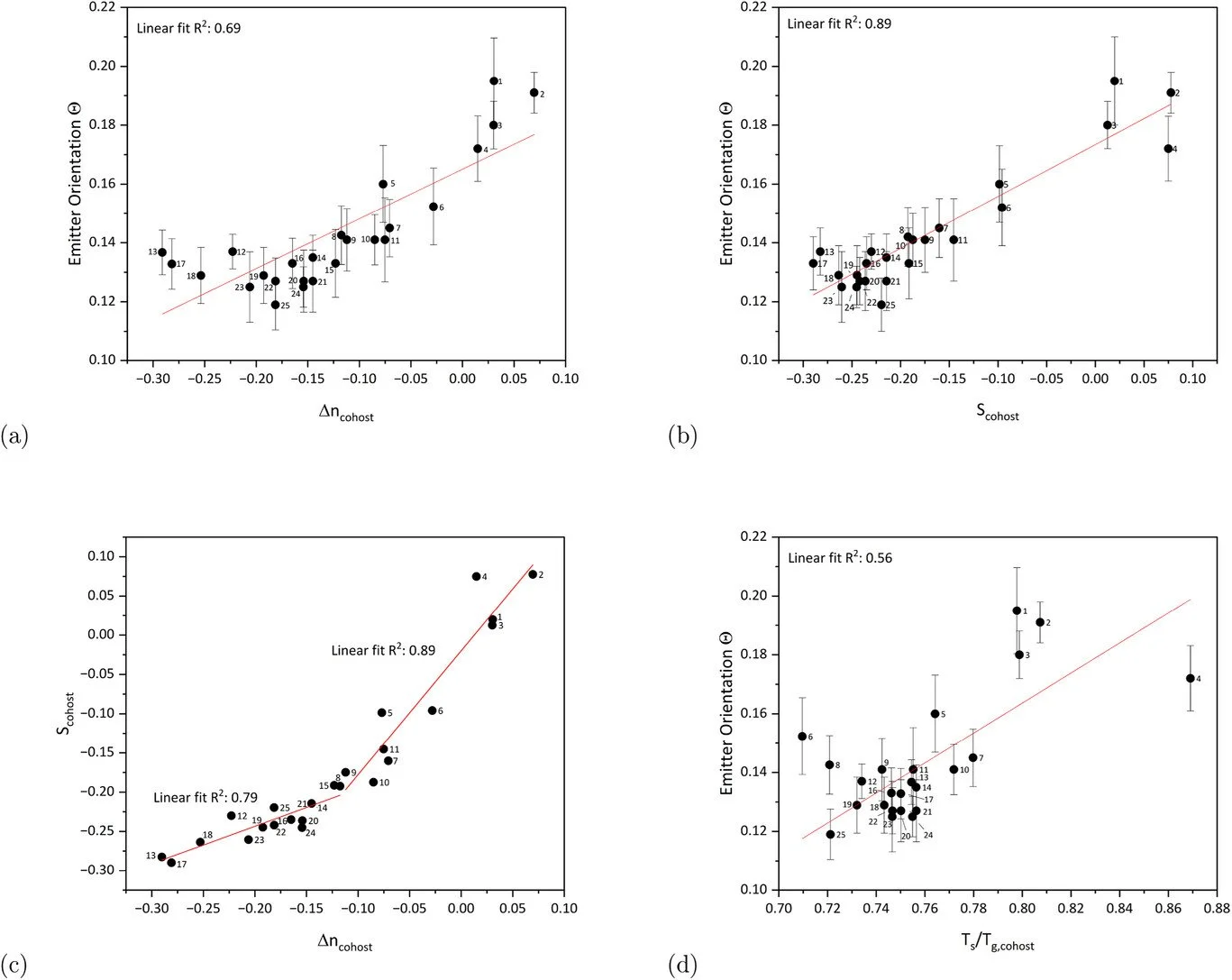
Preferential horizontal emitter orientation is a known route to higher OLED outcoupling. This study shows that the host's optical anisotropy is a decisive factor for tuning the TDM orientation of a phosphorescent Ir(ppy)3-derived emitter in vacuum-deposited guest-host systems: hosts with negative S / negative birefringence lead to stronger horizontal alignment (lower Theta) across 25 cohost materials. Optical simulations and device analysis explain why the EQE gain can be limited by emission-layer birefringence and by changes in emission-zone position driven by the cohost composition.
Publication details
Authors: Binh-Minh Nguyen; Jonas Krober; Philipp Schutz; Klaus Ruhland; Falk May; Wolfgang Brutting
Journal: Advanced Optical Materials
Year: 2026
Fluxim tools used

How Phelos was used in this paper (measurement workflow)
The authors used Fluxim's PHELOS to experimentally determine the emitter transition dipole moment (TDM) orientation via angular-dependent photoluminescence (ADPL):
They co-evaporated the emissive guest-host (G-H) film on fused silica and mounted it with an index-matching fluid on a rotatable cylindrical lens (this is the PHELOS ADPL configuration used to capture angle-resolved emission).
The sample was excited from the top with a 365 nm UV LED.
The PL emission was collected through the cylindrical lens, while the lens was rotated in front of a polarizer and an optical fiber connected to a CCD spectrometer (400–850 nm).
The PL intensity was recorded for both s- and p-polarization over angles from -90 degrees to +90 degrees in 1 degree steps.
The resulting angular radiation patterns were then analyzed using a wave-optical dipole-model simulation: the s-polarized spectrum was first fitted to determine film thickness, and with thickness fixed, the p-polarized spectrum was fitted to extract the orientation parameter Theta.

How Setfos was used in this paper (simulation workflow)
The authors used Fluxim's SETFOS for wave-optical OLED outcoupling simulations based on an emissive dipole model to connect orientation/birefringence to the measured EQE trends:
They performed wave-optical simulations of light outcoupling using SETFOS (Fluxim AG), explicitly stating it is based on an emissive dipole model similar to a cited reference.
Inputs to SETFOS were the OLED layer stack (layer thicknesses and optical constants n and k), plus the emitter orientation and emitter location; the emitter quantum efficiency was assumed to be unity for the optical analysis.
Outputs included the power dissipation split into optical channels (direct emission to air, substrate modes, waveguided modes, surface plasmons, and re-absorption). With unity IQE, the simulated outcoupling to air corresponds directly to EQE.
To isolate the role of orientation and anisotropy, they also report a simplified optical stack (Figure 6b) with 90 nm HTL and 35 nm ETL and constant optical parameters (n = 1.7, k = 0), then varied Theta from 0.2 to 0.1 and compared scenarios including different birefringence assignments and different emission-zone locations/profiles.
Why this research matters
Shows host optical anisotropy (S, Delta n) as a practical design lever for phosphorescent emitter orientation.
Explains why orientation-driven EQE gains can be reduced by birefringence-related optical losses and emission-zone shifts.
Connects orientation measurements to stack-level optics using ADPL + dipole-model outcoupling simulations.
Keywords
OLED, phosphorescent emitter, Iridium complex, Ir(ppy)3 derivative, transition dipole moment, emitter orientation, Theta, guest-host system, cohost materials, optical anisotropy, birefringence, order parameter S, angular-dependent photoluminescence, ADPL, light outcoupling, dipole model, emission zone
FAQs
Q1: What host properties correlate with emitter orientation in this work?
A1: The emitter orientation (Theta) correlates with the host order parameter S and birefringence Delta n across the studied cohosts.
Q2: Why can EQE gains be smaller than expected even with improved orientation?
A2: The paper attributes this to the effect of emission-layer birefringence on optical mode coupling (including lossy modes) and to changes in emission-zone position linked to cohost composition and charge balance.
Q3: How were orientation and optics evaluated?
A3: Orientation was extracted from ADPL (Phelos), and light outcoupling was analyzed with the emissive dipole model using Setfos.