

Vitios

Compact imaging tool for solar cell scale-up. Identify spatial inhomogeneities with confidence.
Vitios combines PL, EL, and IR imaging together with electrical characterization. Together with software for seamless measurement customization and embedded post-processing techniques.
Solar cells scale-up, stressing experiments, new deposition methods all have direct impact on the performance as estimated with a JV. But electrical measurement do not contain spatially resolved information? Imaging of solar cells helps you locate and identify spatial inhomogeneities of your films and full-devices.
Why Vitios
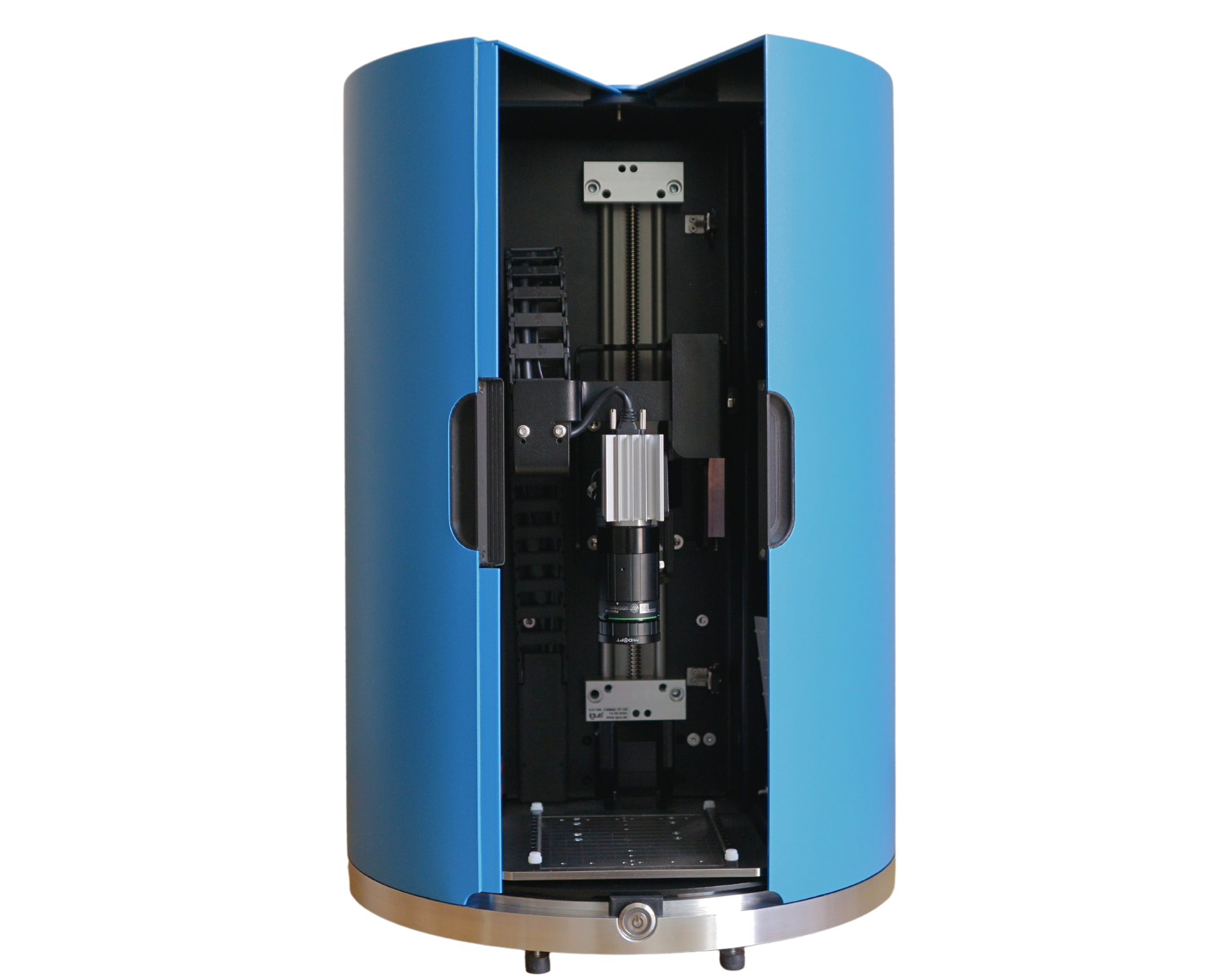
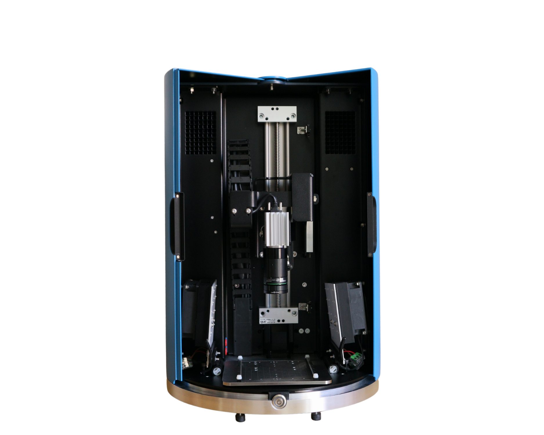
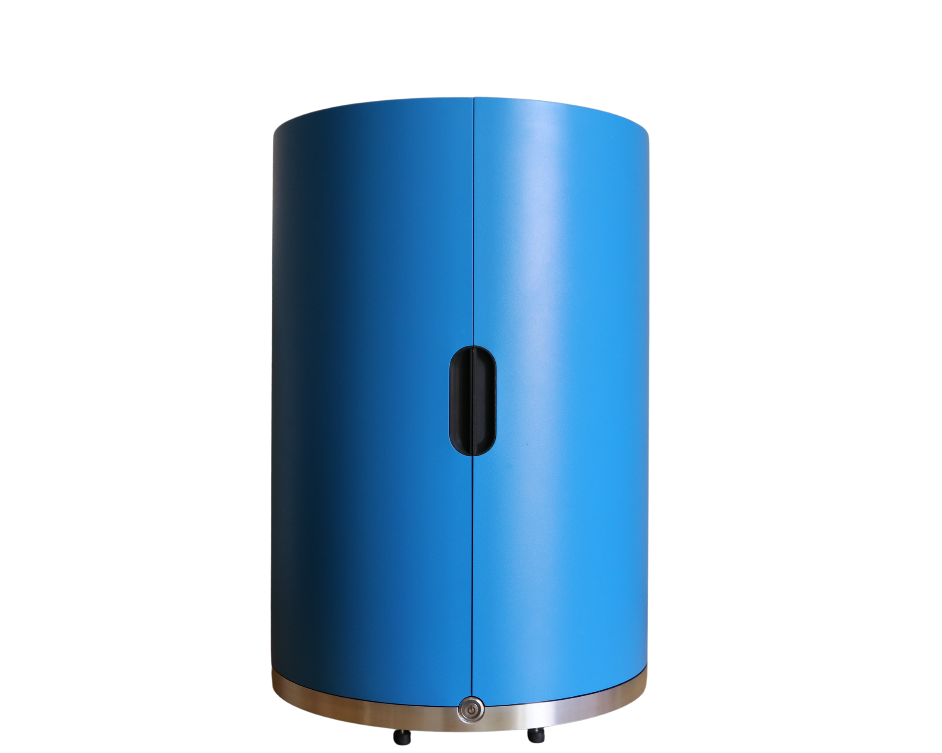
Vitios is the best-balance between measurement resolution, reliability, flexibility and setup simplicitiy. It streamlines quick checks of the film quality and in-depth opto-electrical characterizations. So you can optimize deposition methods and device scale up with ease.
Compact, easy to setup, swiss-knife platform for solar cell imaging. Tested and developed by PV scientist. It is an all-in-one system that integrates photoluminescence (PL), electroluminescence (EL), illuminated and dark lock-in thermography, as well as electrical characterizations (JV and impedance).
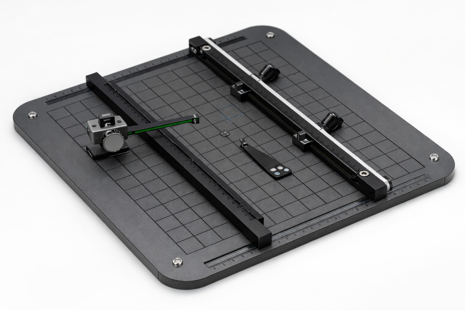
Equipped with 4-wire contacting probes adapt for any device layout: lab-scale single junction (bottom contact or top contact)and tandem sample(top-bottom contact), or minimodules with encapsulation.
Industry-leading precise and reliable hardware combined with an intuitive software interface that allows users to fully customize their measurement settings.
Typical analyses include:
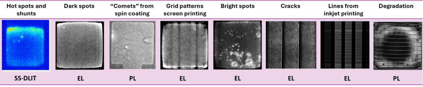
detect spatial inhomogeneities and defects
investigate recombination behaviour using EL and PL imaging
identify dissipative loss mechanisms using lock-in thermography
study transient phenomena linked to ion redistribution
correlate imaging data with electrical measurements
This integrated approach allows researchers to move from observation of spatial patterns to physical interpretation of device behaviour.

Get a quote for Vitios
QUESTIONS?
Talk to Vitios Product Manager,
Dr. Antonio Cabas Vidani
Email: info@fluxim.com
Telephone.: +41 44 500 47 70

Powerful software
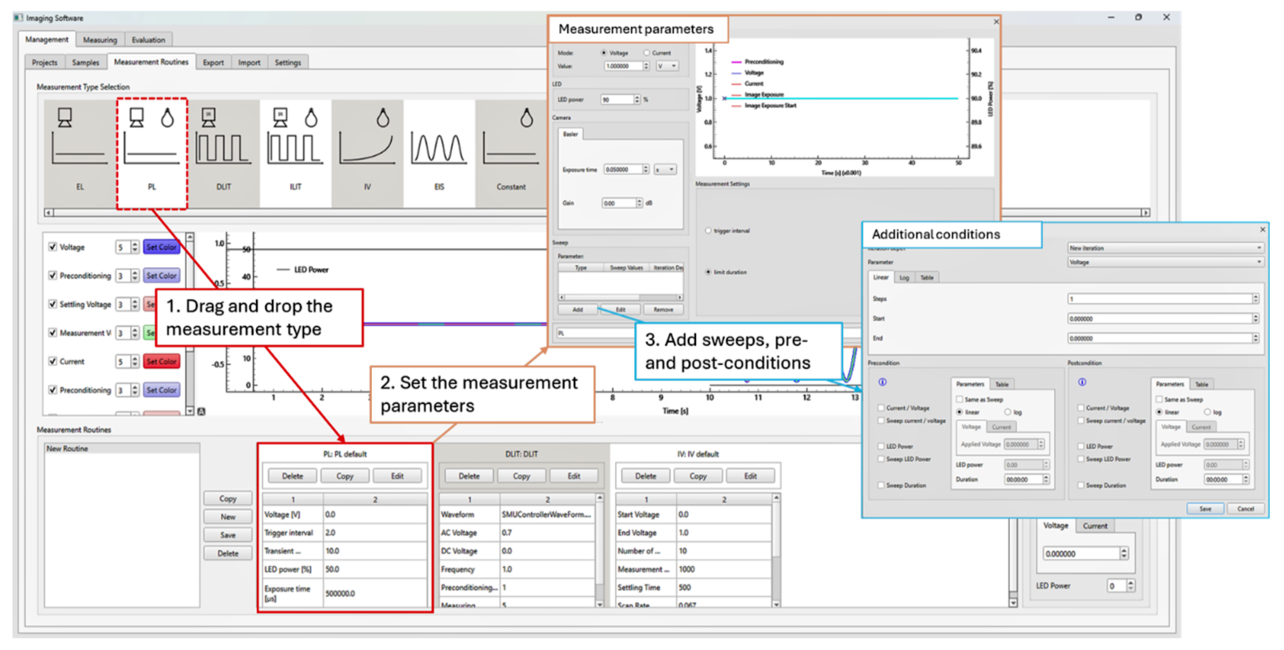
We envisioned a software to quickly transition from fast single-shot measurements to extended routines combining all optical and electrical measurements. The creation of a routine includes the addition of parameter sweeps as well as pre- and post-conditioning your sample. You have full control of what is applied to your sample.
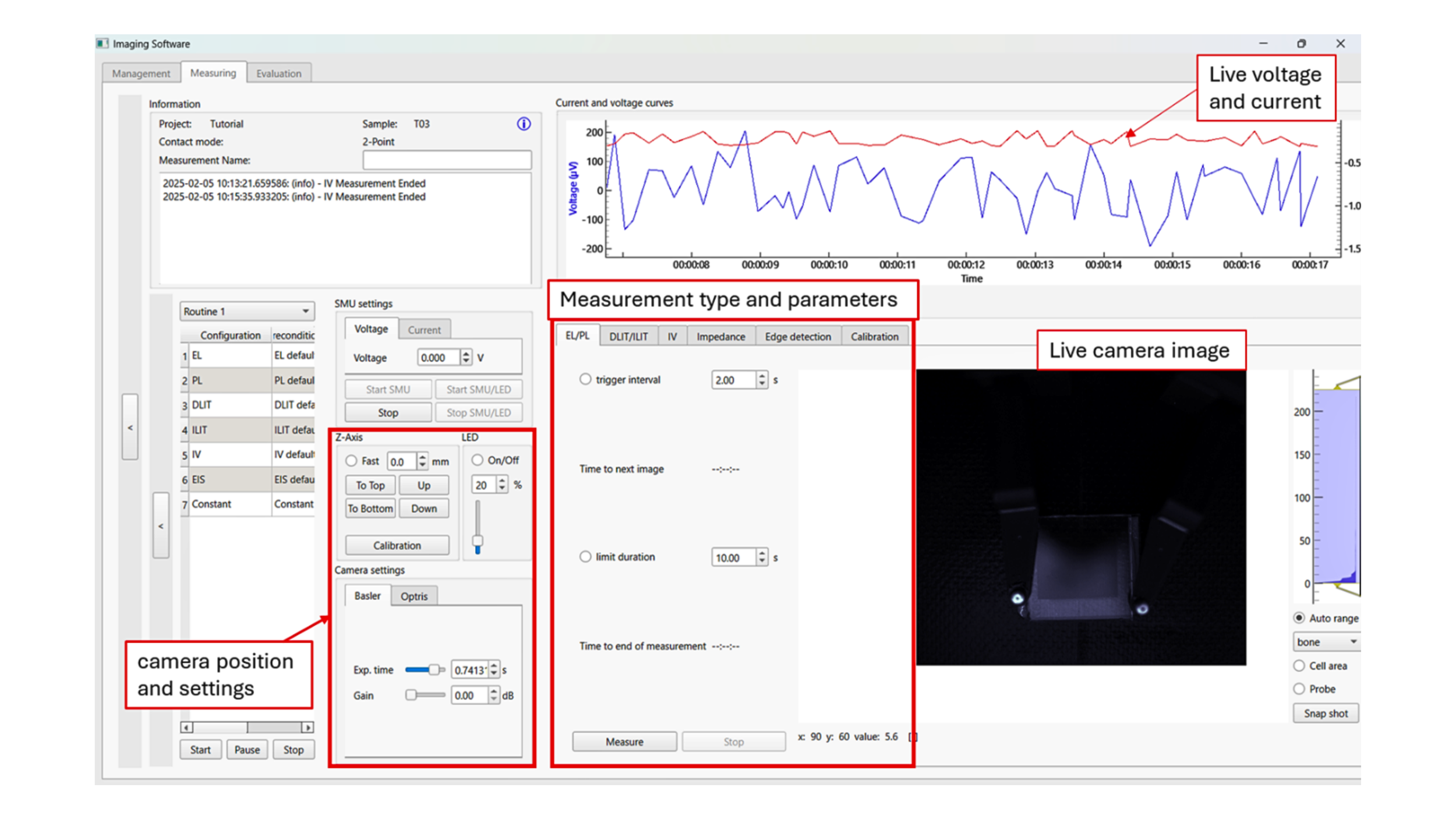
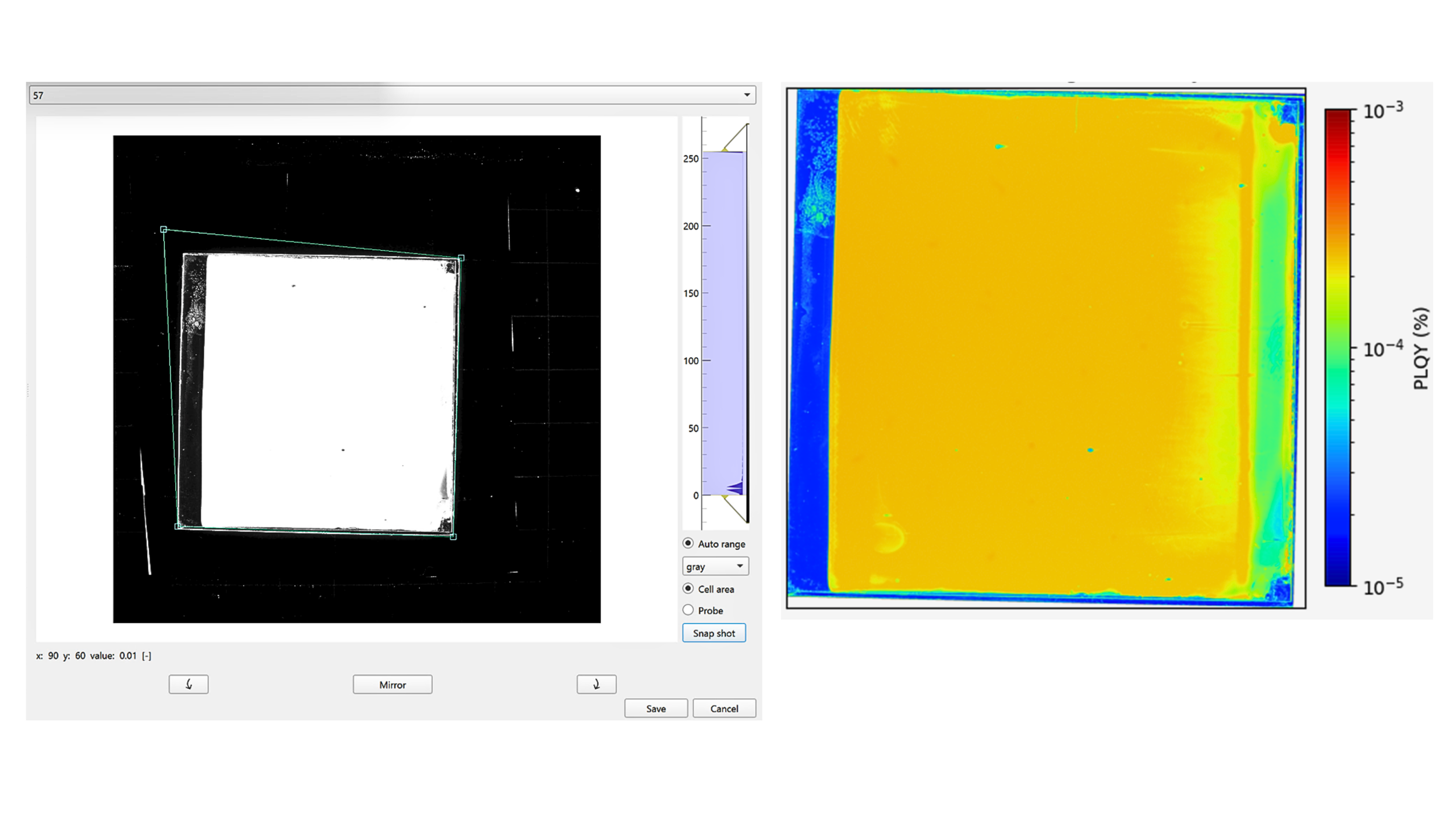
The corner detection feature to define the active area that you want analyse of your sample. On top of that, the software includes post-processing scripts to obtain PV-relevant information from your images. The post-processing include: PLQY, sunsPL, deltaPL for charge extraction, pseudoJV, sunsVoc, resistance imaging and many others.
The ΔPL method for local charge extraction

Photoluminescence images at Voc and Isc with a ΔPL map showing local charge extraction behaviour and transient PL signals for multiple devices.
Vitios supports photoluminescence imaging combined with bias application. The ΔPL method is a perfect example. With the formula ΔPL = PL(Voc) − PL(Isc) it helps visualize spatial variations in local charge extraction. This is particularly useful when assumptions such as a spatially uniform quasi-Fermi level splitting (QFLS) under bias are not justified.
Vitios for perovskite materials
Perovskite solar cells exhibit time-dependent luminescent behaviour after a voltage or light bias is applied. These transients are widely attributed to processes such as ion migration and evolving recombination dynamics within the device.
Vitios enables spatially resolved transient electroluminescence and photoluminescence measurements and analysis to help researchers interpret these effects.
Open circuit
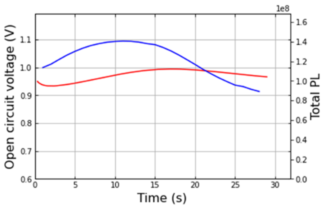
At open circuit: PL peaks around 10 s after light goes ON. More complex Voc trend
Constant V ≈ 0 V
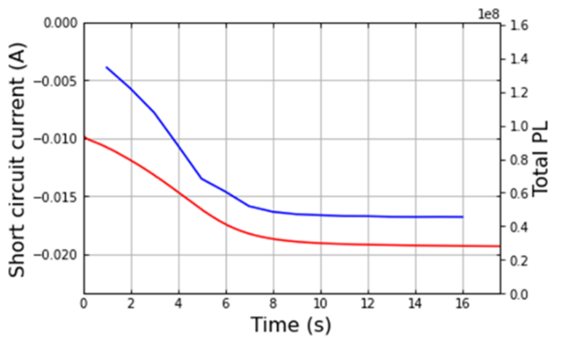
At short circuit: monotonic increase in Isc, and decrease of the PL signal
Transient Electroluminescence
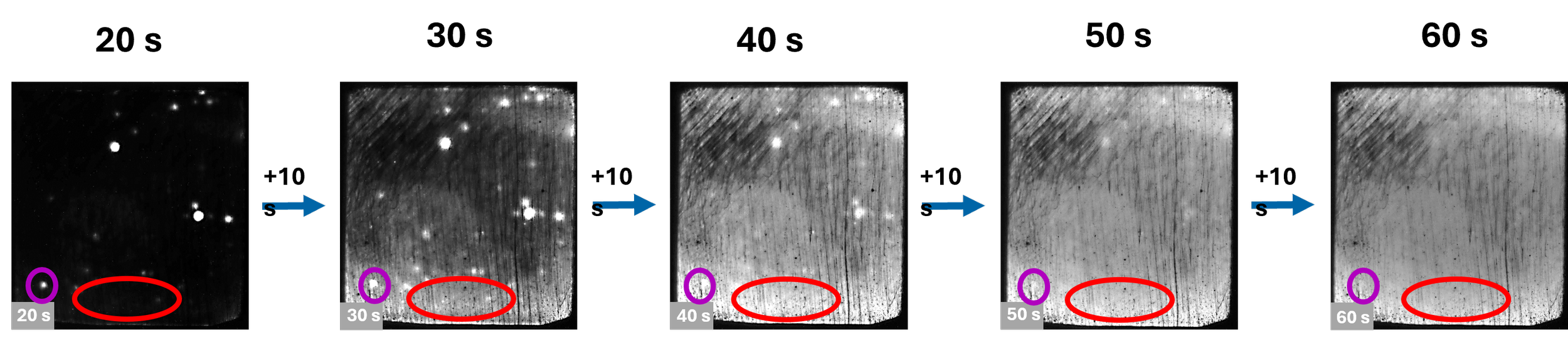
By tracking how EL intensity evolves in different regions of a device, it becomes possible to relate measured behaviour to physical processes known to occur in perovskite devices.
Typical analyses focus on phenomena associated with:
redistribution of mobile ionic species within the device
changes in recombination dynamics influencing radiative emission
differences between local bright spots and the surrounding active area
transient behaviour interpreted alongside steady-state electrical measurements
DLIT vs SS-DLIT
DLIT (dark lock-in thermography) applies short pulses of voltage (light in the case of ILIT). Due to lateral heat diffusion, it does not allow to visualize the impact of mobile ions on power dissipation.
With small-signal DLIT (SS-DLIT) Vitios applies a preconditioning voltage and a sinusoidal voltage on top for additional heat contribution. The device gets into a quasi-steady state. The ions can redistribute and influence the current.
The amplitude image is in phase with the modulation and carries information about the dissipated power. The phase image is correlated to material properties.
EL transient curves illustrating how ion density and ion mobility influence recombination dynamics in perovskite solar cells.
![Line graph titled 'Measurement: EL Transient' showing transient EL intensity over time. The x-axis is labeled 't [s]' from 0 to 60 seconds, and the y-axis is labeled 'EL Intensity [Counts]' from -10 to 80. Two lines: a red line representing 'Transient EL Intensity of Active Area' and a purple line representing 'Transient EL Intensity Highly Emissive Spot.' The purple line peaks around 75 counts at approximately 20 seconds, then gradually decreases. The red line peaks around 30 counts at about 25 seconds and then declines.](https://images.squarespace-cdn.com/content/v1/6679cd2df099450d2239eee2/4c105d05-f8ed-4d96-80d0-076d115cf5a5/vitios-ion-mobility-luminance-transient-modelling.png)
Time-resolved electroluminescence images (20–60 s) showing spatial evolution of recombination patterns in a perovskite solar cell.
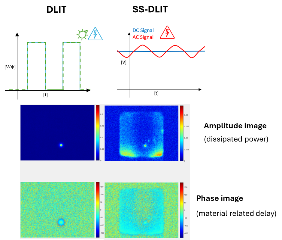
DLIT and SS-DLIT lock-in thermography amplitude and phase maps with excitation waveform used for spatial defect analysis in perovskite solar cells.
Vitios Applications
Vitios is designed for teams working on:
perovskite process optimisation and quality control
stability and degradation mechanism studies
diagnosing shunts, pinholes, resistive losses and recombination hotspots
ion-driven transients
Vitios Specifications
| Category | Capabilities |
|---|---|
| Image post-processing and analysis |
|
| Illumination source |
|
| Electrical characterization |
|
| Sample type |
|
Frequently Asked Questions
-
Vitios is used to analyse perovskite solar cells by combining EL/PL imaging, lock-in thermography and physics-based simulation to identify loss mechanisms linked to ions and recombination.
-
Vitios supports EL (steady-state and transient), PL (steady-state and transient) and lock-in thermography including DLIT, ILIT and SS-DLIT.
-
Because mobile ions can create slow transients and spatial effects that are hard to interpret from electrical data alone. Modelling helps connect observed patterns to ion density, mobility and recombination pathways.
-
Yes. Multi-imaging can reveal spatial inhomogeneities such as shunts, pinholes and contact issues and help determine which features correlate with performance losses.
Talk to us about your setup
Tell us your device architecture (planar/mesoscopic, encapsulated/unencapsulated, cell/module format) and what you want to learn (defect root cause, ion dynamics, recombination pathway). We will recommend a measurement + modelling workflow.