Optimize Micro-Textures for Increased Light Extraction in Flexible, Curved Displays
Flexible electronics are reshaping our gadgets, making them smaller and more powerful. They're mostly hidden away in our devices, but with curved displays, this technology really comes to life, allowing us to directly interact with the innovative shapes they enable.

Figure 1: Curved display in a smartphone (left) and a prototype device (right). source: engadget and flexenable
Curved displays have become widespread since their first introduction into the consumer market with the Samsung Galaxy Round and LG G Flex in 2013. Initially, curved displays were dominated by small OLED displays on smartphones whereas later on large LCD panels were shaped to enhance the user experience. In the near future, curved displays will become even more widespread, especially in the automotive industry.
To have a consistent user experience a curved display needs to meet high requirements to deliver a better experience compared to traditional displays. These requirements include homogeneous color purity and display brightness over a large area and angular range (Figure 2). To understand and fulfill these requirements the large area electro-optical simulation software Laoss is used to optimize the optical structure for improved light outcoupling.

Figure 2: Image of a bent, flexible display backlight unit. Pronounced edge darkening is visible due to non-lambertian emission characteristics.
The findings discussed here have been conducted in the EU Horizon2020 program within the PHENOmenon project in collaboration with FlexEnable. The results shown here are part of a presentation at SID 2020 and the IMID conference.
Simulation
An essential part of curved LCDs is the backlight units (BLU) which have to ensure a high spatial and angular uniformity of the display brightness. Generally, the edges of a curved display will appear darker due to the non-Lambertian emission characteristics of the display, even worse, the color might shift at these edges when the angular emission characteristics is wavelength-dependent. These effects lead to a decreased user experience and need to be avoided. Here we will show how a backlight unit of an edge-lit curved LCD display can be improved using the Laoss simulation software to deliver a uniform brightness over a large viewing area.
At the core of Laoss is a 3D ray-tracing engine. The structure of the simulated device is defined via layers and interfaces, to which optical properties are attributed. In addition to the thickness, the layer properties contain the optical constants (refractive index and extinction coefficient) as a function of wavelength. Ray propagation at interfaces is described either via Fresnel equations for simple refraction, or by angle-dependent transmission and reflection coefficients, or, in the case of diffuse scattering, by a bi-directional scattering distribution function (BSDF) read from external files. In this way, behavior inferred from coherent sub-wavelength optics can be combined with ray optics for a multi-scale optical simulation. The topography of an interface, on the other hand, is specified either via an XYZ topography or via an explicit surface including the triangulation required to run the ray-trace algorithm. As a special feature of LAOSS, user-defined or generated topographies can be transformed onto cylindrically curved surfaces with an arbitrary radius of curvature. To simulate and optimize the backlight unit, we define the simulation domain to be a narrow stripe originating at the edge where the LEDs illuminate the backlight unit (Figure 3).

Figure 3: Simulated backlight unit (BLU) with the simulation domain.
More specifically, the simulated components are the (see also Figure 4)
1. Light source: angular dependent white LED spectrum.
2. Specular reflector: reflection using optical constants for silver.
3. Light guide: position-dependent bottom roughness for uniform light outcoupling over a large area.
4. Diffuser sheet: widen the out coupled beam implemented using a corresponding BSDF for the top surface.
5. Brightness enhanced film (BEF): 3D surface topography in the shape of position-dependent asymmetric triangular prisms.
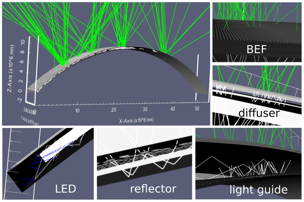
Figure 4: Simulated components in the curved display backlight unit.
If you want to evaluate LAOSS, we will be happy to help you
Results
Benchmark known surface textures with measurements
It is important to know how well the Laoss simulation performs for known surface structures and compare them to measurements. Figure 5 shows simulated and measured angular emission characteristics for a flat and curved backlight unit. Overall, there is an excellent agreement between simulation and measurement.
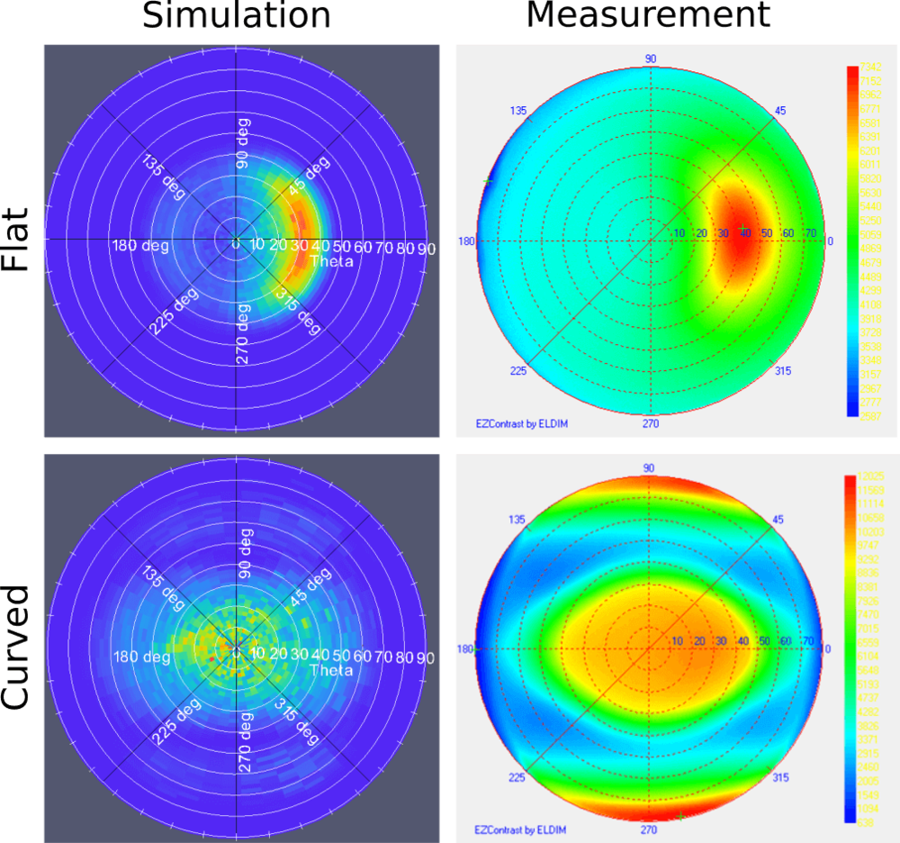
Figure 5: Simulated (left) and measured (right) angular emission characteristics for a flat (top) and a curved (bottom) commercially available backlight unit (BLU) with known micro-structure. Overall a very good agreement can be observed, where the simulation captures more details of the emission characteristics.
Use and optimize triangular micro-texture for enhanced light outcoupling
In the next step, the brightness enhancement film on top of the backlight unit is optimized using a position-dependent asymmetric triangular grating (Figure 6). The goal is to reduce the edge darkening as shown in Figure 1. This optimized microstructure enhances light outcoupling and brightness uniformity much better than other commercially available simulated microstructures. With this optimized micro-texture, a brightness uniformity of over 95% was achieved in the simulation.

Figure 6: Optimized brightness enhancement film (BEF) to direct the emitted light towards the user. The curved BEF is shown in the bottom at the middle and the detailed views around show a zoomed-in version of the asymmetric triangular micro-structure on each end and the middle of the BEF. This optimized micro-structure guides the emitted light towards the user and ensures a homogeneous brightness over the whole curved display area.
In conclusion, the large area electro-optical simulation software Laoss has been used to optimize a flexible, curved display backlight to increase overall brightness as well as brightness uniformity.
If we have sparked your interest to simulate and optimize flexible displays using Laoss get in contact with us.
References
SID 2020 Session 64: Simulation of Beam Shaping by Micro-Textures for Curved Displays
presented by Urs Aeberhard, Fluxim AG, Winterthur, Switzerland