How a Master Thesis Project Developed into the New Setfos Advanced Excitonics Module
😃There is a brand new Setfos Module!
We recently launched version 5.2 of our advanced simulation software Setfos. On top of the many new features that were deployed we developed a new module: The Advanced Excitonics Module (AE) that features a novel 3D model for Excitons based on a Master-Equation approach. This module is focused on OLED development, we’re very pleased that several research groups have already started using it but we want more customers to try it out (if you already have the drift-diffusion module then there is no charge for the first year).
🤔 So tell me more about the Setfos Advanced Excitonics Module?
Setfos development has always been aligned with what researchers tell us they want in order to help advance their LED and Solar Cell research. Whether it’s a direct feature request from a customer or a problem posed in research that we think we can help solve, then we’ve built it. The AE Module is a great example of this process. It started out as a Master Thesis project by our colleague Simon Zeder which lead to the publication of the paper below and evolved into the new module.
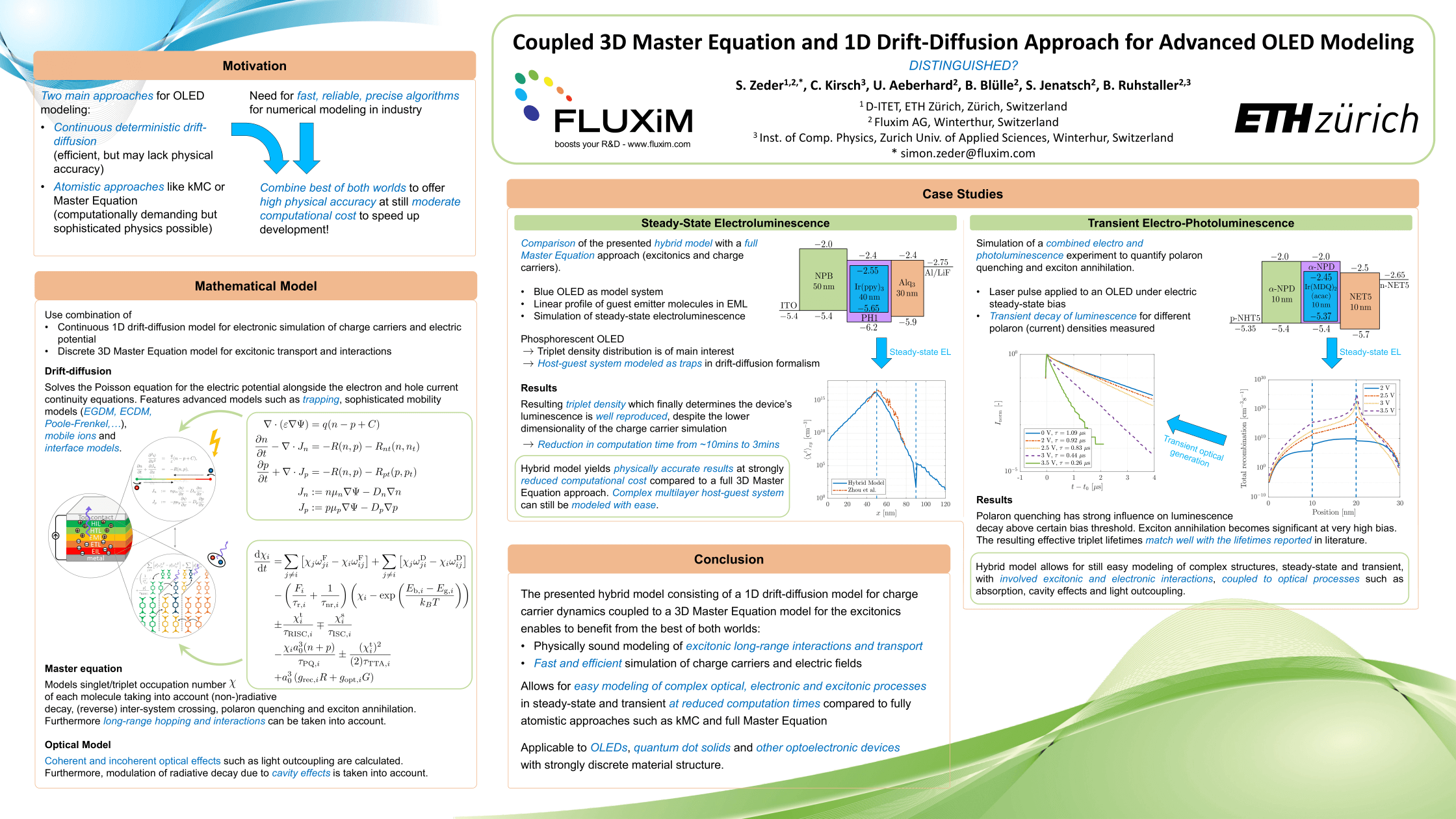
Coupled 3D master equation and 1D drift‐diffusion approach for advanced OLED modeling
Simon Zeder, Christoph Kirsch, Urs Aeberhard, Balthasar Blülle, Sandra Jenatsch, Beat Ruhstaller
First published: 21 April 2020 https://doi.org/10.1002/jsid.903
Abstract:
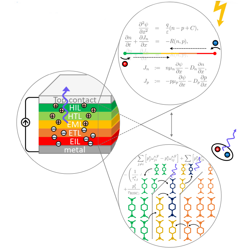
A novel simulation approach for excitonic organic light-emitting diodes (OLEDs) is established by combining a continuous one-dimensional (1D) drift-diffusion (DD) model for the charge carrier dynamics with a three-dimensional (3D) master equation (ME) model describing the exciton dynamics in a multilayer OLED stack with an additional coupling to a thin-film optics solver. This approach effectively combines the computational efficiency of the 1D DD solver with the physical accuracy of a discrete 3D ME model, where excitonic long-range interactions for energy transfer can be taken into account. The coupling is established through different possible charge recombination types as well as the carrier densities themselves. We show that such a hybrid approach can efficiently and accurately describe the steady-state and transient behavior of optoelectronic devices reported in the literature. Such a tool will facilitate the optimization and characterization of multilayer OLEDs and other organic semiconductor devices.
SID Display Week Distinguished Poster Prize
The paper was presented as a poster at last year’s SID Conference and subsequently won a Distinguished Poster Paper Award
🧐 So you’re saying the new AE Module will help facilitate further optimization and characterization of OLEDs?
Yes! As a powerful alternative to the existing 1D exciton model, the novel Master-Equation approach mimics the discrete distribution of different molecules in 3D space, and thus captures physical processes like the non-local energy transfer in a more realistic manner. In particular, the new model allows one to study:
* Energy transfer across layer interfaces
* Excitons in material blends (e.g. host-guest systems)
* Correlated and uncorrelated energetic disorder
The new module can be coupled to emission, absorption, and drift-diffusion for fully coupled simulations and will allow you to consider long-range transport of excitons via Förster and Dexter processes, also across layer interfaces.
And for those of you working on solar cells and other organic semiconducting devices, we are hoping to release an extension featuring a charge dissociation model in the near future.
😲 Great, show me how it works.
No problem, the following example will present a fully coupled OLED simulation that uses the Master Equation model for excitons.
The TADF OLED stack and several input parameters (excitonic rates, energy levels, emission spectra) were taken from a publication by the group of Prof. Adachi. The energy level diagram is shown in Fig.1. The EML is a host-guest system and is here modelled as follows. The transport levels are set according to the HOMO and LUMO levels of the host (mCBP). The mCBP density of states N0 is reduced to 8·10²⁶ m⁻³ in order to represent the host-guest volume ratio of 0.8. Correspondingly, the guest material is mimicked as hole and electron traps with a trap density of 2·10²⁶ m⁻³ and a trap depth that reflects the nominal differences of HOMO and LUMO levels of the two materials. The recombination on the host is considered as Langevin type, while trap-trap recombination is enabled for the guest material.

Fig 1. a) Energy level diagram as shown in setfos. The host-guest EML is modelled by considering HOMO/LUMO of the host (mCBP) and the guest as hole and electron traps. (b) Used exciton energies (full black lines) and band gap energies (blue dashed line) of all materials.

Fig. 2 (a) Energy level diagram as shown in setfos. The host-guest EML is modelled by considering the HOMO of the host (mCBP), the LUMO of the guest and hole traps with SRH. (b) Used exciton energies (full black lines) and band gap energies (blue dashed line) of all materials.
The master equation model is enabled for all semiconducting layers, except for the HAT-CN injection layer. All transport layers consist of just one material, thus, in the Master-Equation one has to define only material 1 parameters. Generation of excitons occurs through Langevin recombination, with prefactors of 0.25 and 0.75 for singlets and triplets, respectively. Binding energies are set according to the nominal difference of exciton energies and bandgap energy of the layer (see Fig. 1 (b)). For the EML we define two materials with a ratio of 0.8:0.2. As described in the previous section, Langevin recombination is the source for exciton generation on the host (material 1), and trap-trap recombination is used to generate excitons on the guest (material 2). Fig. 3 shows a screenshot of the GUI for ME properties of the guest material. As we are dealing with a TADF emitter, we enable the Triplet –> Singlet transfer to calculate also the reverse intersystem crossing (risc) contribution.

Figure 3: Master equation settings for the guest (material 2) of the EML.
If you want to use Setfos 5.2, the evaluation is FREE
General Förster and Dexter radii are set to 1.5 and 0.8 nm, respectively, in the Master equation settings tab. Note that Setfos currently only considers one Förster and one Dexter radius. Despite this model restriction, host to guest transfer is still more likely due to the lower exciton energy of the guest. The same also holds for transfer to other layers.
Finally, we couple the radiative recombination in the EML, EBL, and HBL to 4 emitters. This is defined in the emitter settings, using the option “ME exciton coupled” with the respective exciton type as distribution. The calculated exciton densities and selected rates are shown in Fig. 4. While the generation of excitons occurs mostly at the EML/HBL interface (see Fig. 4b), the steady-state distribution shows a less steep decrease of excitons in the EML but also in the transport layers (see Fig. 4a). The radiative decay of singlets on material 2 in the EML (i.e. the emitter) is dominating all the other radiative rates in the stack. Therefore, the emission spectrum (not shown here) is almost solely given by the guest spectrum, and surely the cavity, but shows almost no feature of the transport layers or the host. In the above first example, we can see that the emission is predominantly occurring from the EML/ETL interface. This is mainly due to the high barrier for electrons at this interface. This is however not what the authors of the original paper (Adachi et al.) report. As the guest concentration in their EML is 20%, it is reasonable to assume that electrons are not injected to and transported on the host (mCBP) but directly through the TADF guest material itself. In order to mimic this situation in Setfos, we, therefore, adapt the simulation in the following.
The only layer properties that need to be adapted are the EML parameters. First, we set the LUMO level in Setfos to the value of the guest, i.e. 3.3 eV. Since the hole trap is still there to represent the guest, the recombination on guest molecules would now be considered as Shockley-Read-Hall (SRH) recombination. We, therefore, enable SRH recombination in the drift-diffusion tab and reduce the Langevin recombination efficiency. Lastly, in the master equation tab of the EML, we change the generation type of material 2 excitons to SRH and adjust the binding energies of both materials in the EML to the new "band gap" of 2.8 eV. The final energy level and exciton diagram are shown in Fig. 2.

Figure 4: (a) Master equation exciton density profile (S = singlest, T = triplets). (b) Generation and radiative recombination rate of singlet and triplet excitons in steady-state. The diffusion of excitons within and across interfaces through Förster and Dexter processes leads to a less redistribution of excitons within all the layers.
In this adapted simulation the charge accumulation at the HBL/EML interface is strongly reduced, leading to a higher current through and emission from the device. First, we note that the total recombination is dominated by the SRH contribution in the EML (see Fig. 5 a). This confirms the suitability of the chosen recombination settings. Most importantly, the exciton densities (Fig. 5 b) are now highest at the EML/EBL interface, which agrees with the report by Adachi et al. One could now also further refine the model and consider further loss mechanisms such as TTA or TPQ.
For a benchmark of the coupled drift-diffusion - master equation model with literature data, we draw your attention back to the paper by our colleague Simon Zeder.

Figure 5: (a) Recombination profile and (b) exciton densities for the adapted simulation.
🙏Thanks, so how do I get the new Advanced Excitonics module?
If your current Setfos license includes the drift-diffusion module then you will be able to use the AE module for free for the first year. Simply update your dongle in the Fluxim License Manager. By clicking on “Check online”, the AE license will be added automatically.
Are you new to Setfos?
Setfos is the leading advanced simulation software for developing solar cells and LEDs. The latest version 5.2 comes with a whole host of exciting updates, not just the new AE module:
• Position- and Time-dependent Sun-Spectrum
• Sweeps over time to compute the total energy yield
• SRH Recombination at Interfaces
• Emission spectrum from nk dispersion
• Extended Exciton Quenching
• Stacked Exciton Diagrams