How ISOS Protocols Are Used to Assess Perovskite Solar Cell Stability
ISOS protocols offer modular, research-driven guidelines for testing the stability of perovskite solar cells under realistic stress conditions like light, temperature, and electrical bias. Unlike rigid IEC tests, ISOS enables comparative studies across labs. For deeper accuracy and reproducibility, intrinsic and extrinsic stability must be tested separately using tools like LITOS or LITOS Lite. Key takeaways: don’t rely only on T80, document all conditions, and use parallel testing setups when possible.
Why ISOS Protocols Matter

Perovskite solar cells (PSCs) show immense promise, with rapid efficiency gains and low-cost manufacturing. However, their long-term stability under real-world conditions remains a major challenge—often overlooked in headlines focused on power conversion efficiency (PCE) records.
To address this, researchers developed the ISOS (International Summit on Organic Solar Cells Stability) protocols: a flexible framework designed to test stability under controlled stressors like heat, light, humidity, and electrical bias. Unlike IEC standards (which are geared toward silicon panels and industrial qualification), ISOS protocols are modular, open, and tailored to emerging thin-film technologies like perovskites.
This article breaks down:
What the ISOS protocols are
How they apply to perovskites
How to interpret T80 and other figures of merit
Best practices for reproducible aging tests
Whether you’re developing next-gen photovoltaics or validating long-term performance, this guide will help you align your stability tests with community standards.
The existing qualification tests of the International Electrotechnical Commission (IEC) were developed to address the field performance of silicon panels. Emerging PV technologies, like PSCs, require tests tailored to their characteristics. To standardize the stability analyses for Organic Solar Cells (OSCs), a series of stressing protocols were grouped into the International Summit on Organic PV stability (ISOS). [Ree11] Likewise, it has been proposed to address the mechanisms that affect the operational stability of PSCs with protocols adapted to this specific technology.
How do we perform aging experiments that are tailored to emerging PVs? A recent Nature Energy Paper [KHEN20] published by some of the most renowned researchers on PSCs provides crucial guidelines, which will be summarized here.
This blog post provides a quick guide to understand the difference between the different ISOS protocols for the analysis of Organic and Perovskite solar cells.
Plan ISOS-compatible stability measurements
Request a configuration for Litos Lite, designed for ISOS-compliant perovskite solar cell stability testing.
Standard ISOS Stability Protocols
The ISOS protocols can be defined through the combination of four stress factors and their variations as follows:
light exposure (visible and UV): dark or 1-sun equivalent;
temperature: ambient, 65°C or 85°C;
ambient contaminants: inert, ambient, controlled humidity;
electrical bias: open circuit (OC), MPP tracking or fixed voltage (positive or negative).
The ISOS tests can be applied to single solar cells, to neat materials, incomplete solar cell stacks, or mini-modules. The main goal is to guarantee results comparability of lab-scale devices among different laboratories. Unlike IEC, the ISOS protocols are not meant to be a standard qualification test and cannot be failed, but the results will improve understanding about the failure modes of the solar cell device under test. The ISOS protocols can be divided into 5 main testing groups, each focusing on a different stressor:

● ISOS-D: dark-storage/shelf-life
● ISOS-L: light-soaking
● ISOS-O: outdoor testing
● ISOS-T: thermal cycling
● ISOS-LT: light-humidity-thermal cycling
Each group is further divided into three levels with increasing control of the testing parameters and it is a step-up in complexity and sophistication of the required laboratory infrastructure. For instance, a sample can be simply stored in the dark with no control on other parameters or stored in the dark at a specific temperature and humidity (Table 1, from ISOS-D1 to ISOS- D3). The different levels are complementary to one another and the lower-level protocols are not less important than the more complex ones. For example, the combination of ISOS-D3 to ISOS-D2 allows investigating the influence of humidity on degradation in the dark.
| Protocol | T (°C) | R% (Humidity) | Environment |
|---|---|---|---|
| ISOS-D1 | Ambient | Ambient | Ambient |
| ISOS-D2 | 65, 85 | Ambient | Oven, Ambient |
| ISOS-D3 | 65, 85 | 85% | Chamber |
Table 1 : Dark storage protocols (ISOS-D) at increasing level of complexity (from ISOS-D1 to ISOS-D3).
You can find the parameters combinations that determine each protocol and its three levels in the Nature Energy Paper.
Purpose of Each ISOS Protocol
ISOS-D (dark storage) tests the tolerance to oxygen, moisture, and atmospheric components (e.g.: CO2, NOx, H2S). An ambient atmosphere promotes the formation of traps, perovskite decomposition, and surface charging.
With ISOS-L (light soaking), migration of defects and ions, as well as phase segregation are accelerated through light exposure. It is essential to mention the type of light source used to perform the experiment as it affects the degradation dynamics, too.
The purpose of the ISOS-O (outdoor) is to have a realistic assessment of device lifetime in a real environment. Even though the climate is specific to the geographical location and cannot be reproduced, field tests provide information on failure modes and correlations between real-weather and accelerated stress conditions.
ISOS-T and ISOS-LT tests (thermal and light-humidity-thermal cycling) aim to investigate the influence of cycling weather conditions (solar radiation, temperature, and humidity), which is more detrimental than constant stressing conditions due to ion migration at the contacts.
As a general rule, temperature stressing serves to accelerate the degradation caused by other factors, but some perovskite materials undergo phase transitions, hence the impact of temperature is less clear and not isolated. It is advisable to use temperatures above the tetragonal to cubic phase transition for MAPbI3.
Additional Protocols for Perovskites
Perovskite Solar Cells present unique degradation mechanisms that deserve specialized protocols. These protocols have been added by the community to the existing protocols suggested for Organic Solar Cells. The specific protocols for PSCs are:
● ISOS-LC: light-dark cycling
● ISOS-V: electrical bias in the dark
● ISOS-I: intrinsic stability testing
The ISOS-LC (light-dark cycling) serves to reveal information about “fatigue” (influence of pre-conditioning and cell history on the present performance) and metastabilities in the perovskite. The latter ones depend on phenomena like ion migration and reversible chemical reactions that are active only with cycling stressing conditions.
With ISOS-V (electrical bias in the dark) a negative or positive bias stimulates ion migration, charge accumulation, and moisture-initiated degradation. Both positive and negative stressing voltages mimic real working conditions. Under illumination, the solar cell operates at MPP or open-circuit voltage if disconnected from the load, whilst a negative bias mimics a shaded solar cell. Recovery conditions in dark storage should be considered after the bias stressing since the charge redistribution is (partially) reversible.

schematic showing factor influencing the stability of a perosvskite PV. Image taken from reference [CHE21]
Eventually, each protocol can be carried out either in an inert atmosphere or with encapsulation in ambient atmosphere. This allows distinguishing between intrinsic and extrinsic stress factors. The latter depends on the cell interaction with the environment, whereas the former includes light, temperature, and electrical bias. The degradation of the encapsulant can overshadow the degradation of the PSC device, hence the necessity for tests that avoid this issue.
Any of the above protocols belong to the ISOS-I (intrinsic stability testing) protocols if it is carried out in an inert atmosphere (like Argon or Nitrogen) and without encapsulation. In this way, it directly addresses the intrinsic stability of the solar cell.
Dos and Don’ts in Stability Testing
To ensure the reproducibility of the ageing experiments, it is good practice to document thoroughly the measurement conditions and the sample preparation. Especially for perovskite solar cells, it is suggested to:
Do also monitor parameters that are not recorded during ageing.
Do carry out the experiment on multiple cells for statistics purposes and to compensate for the low reproducibility of PSC.
Don’t refer to the performance of a different device than the one used for the ageing experiment.
Don’t measure only fast JV scans.
Do mention preconditioning of previous stressing history of the sample.
Do claim details about the light source (irradiance, spectrum, and type of light).
Do measure JV periodically during ageing. Preferably in quasi-steady-state. Better MPP tracking (MPPT). Best MPPT coupled with periodical JV and non-destructive characterizations.
FLUXiM developed 3 different instruments to assess the stability of Perovskite Solar Cells


T80 and Other Figures of Merit
As for the measurement, also the analysis of the results needs to be reliable. Figure-of-merit (FOM) parameters help to compare different devices and a typical one used to evaluate the stability of a solar cell device is the time required to reach a specific percentage of the initial efficiency.
The most common is the T80, which is the time passed during the ageing experiment to reach 80% of the initial efficiency. Despite the simplicity of the concept, it is not straightforward to determine the T80 in the case of perovskite solar cells. PSC devices under continuous stress have shown a variety of trends (Figure 1):
rapid initial efficiency decrease (the so-called burn-in effect) (Figure 1e);
efficiency recovery after removal of the stress (Figure 1g);
a non-monotonic behavior with max efficiency after hundreds of hours (Figure 1f).
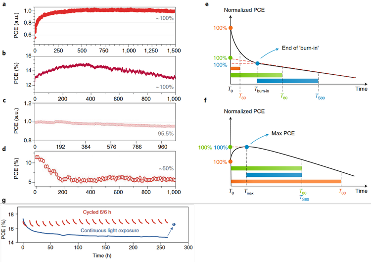
Figure 1: (a-d) possible PCE profiles upon ageing under 1-sun illumination. (e) PCE evolution with time in the case of “burn-in” effect. (f) PCE evolution with time in the case of non-monotonic behavior. (g) PCE evolution of PSCs exposed to continuous (blue curve) or cycled (6/6 h, red curves) illumination by white-light-emitting diodes.
For this reason, it is difficult to determine the effective initial efficiency. Variations of the FOM T80 can accommodate these uncertainties. TS80 is the stabilized T80 time, and it is the 80% of an arbitrary “stabilized” efficiency after the burn-in or the max absolute efficiency for a non-monotonic evolution. In case of efficiency recovery after stress removal or cycled stress, the T80 needs to be corrected accordingly.
State-of-the-art PSC devices need more than 1000 hours to reach the T80, but ageing for longer times is a challenging task for some laboratories. In such case, the efficiency after 1000 hours (η1000), expressed as a percentage of the initial efficiency, can be used as a stability FOM.
Eventually, once PSC devices will become more stable, the FOM T95 should be considered, which is also in accordance with the IEC procedures.
PSCs might also present a recovery of the PCE when the illumination conditions are cycled (light-dark cycling, see Figure 1g). The efficiency can recover after stress removal or, on the contrary, when stress is applied after a resting period (also known as fatigue-like behavior).
To account for the recovery in an MPP tracking experiment, the sample PCE should be measured after a resting period of several hours in the dark. This obtained value is used to renormalize the MPP tracking decay curve. [Sal18]
In the case of outdoor testing (ISOS-O) where the light exposure follows the diurnal cycle, the performance measured with the daily energy output and the FOM T80' will be the 20% drop in the daily output. [Kehn18]
The device lifetime obtained with the specific ageing conditions of a single protocol is an important figure-of-merit to understand the improvement of your sample. On the other hand, the combination of ISOS protocols that differ exclusively in one parameter allows you to appreciate the impact of a stress factor on the device. Figure 2 is a graphical representation of how you can select the ISOS protocols to investigate the influence of a single stress factor: by fixing light, electrical bias, and temperature (blue arrows) you can study the influence of various atmosphere conditions; by fixing temperature, atmosphere conditions, and light (green arrows) you can study the influence of the electrical bias.

Figure 2: combination of parameters (left side) to understand the impact of a single stress factor (right side).
Accelerated Aging & Arrhenius Models
State-of-the-art PSC can now reach up to more than a thousand hours of T80 lifetime. While this is far from the requirement of >20 years lifetime for commercial applications, it is challenging for some laboratories to test for such long time. A solution to the problem is the accelerated ageing. This requires stressing the device at harsher conditions than standard operating conditions to quantify the acceleration factor (AF), which helps to estimate the standard lifetime with a faster test.
To accelerate the ageing, it is common practice in organic and silicon solar cells to stress under high temperature or high illumination intensity. The AF for each stress can be derived from a physical model, only if the occurring degradation mechanism is the same as at standard conditions. For instance, by stressing at increasing temperatures, one obtains the dependence of efficiency degradation rate with temperature. The degradation rate at lower temperatures can then be extrapolated from the trend at higher temperatures.

In a recently published paper in Science, Zhao et al. [Zha22] stressed an all-inorganic perovskite device at 35°, 59°, 85° and 110°C (Figure 3 left). They observed an Arrhenius temperature dependence of the efficiency degradation rate from which they could extract the temperature-dependent degradation rate. In their case, AF was defined as the ratio between the degradation rate at high temperature and the degradation at low temperature. This allowed them to estimate a lifetime at standard operating conditions (1 sun, 35°C) of 3531 hours. (Figure 3 right)


Figure 3: (left) PSC stability test at increasing temperature (from 35°C to 110°C). (right) PCE against equivalent ageing time at 35°C defined as aging time (in units of hours) multiplied by the acceleration factor for increasing ageing temperature (from 35°C to 110°C).
Conclusion: Tools and Best Practices
Emerging thin-film photovoltaic technologies, like perovskite solar cells, have reached a promising performance, but the low reproducibility obstacles the possibility to go from laboratory- to industrial-scale. As thin-film photovoltaic materials present different properties from silicon modules, tailored ageing experiments are required.
ISOS protocols, originally created for organic photovoltaics, can be adapted to perovskite unique features and used to ensure comparability of ageing tests performed at different laboratories.
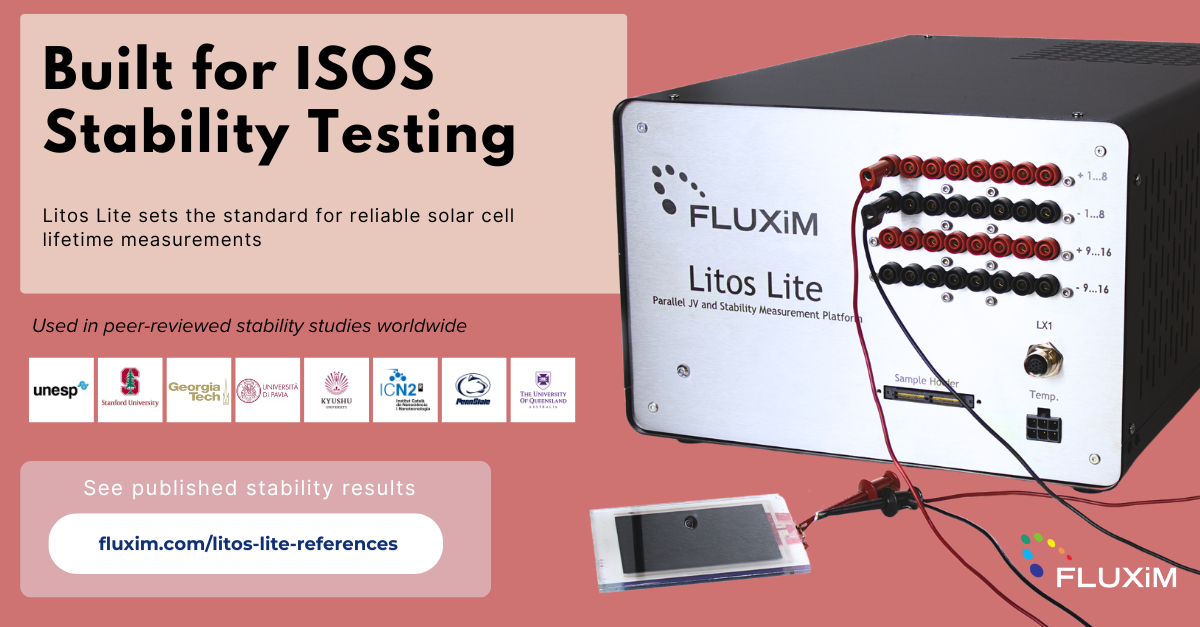
FLUXiM has been working for over a decade to support the development of innovative solar cells. Our stability assessment tools LITOS and LITOS LITE were released in early 2020 and have been developed for solving solar cell stability issues, whilst adhering to the standards set by ISOS. The instruments are designed to run parallel JV and stability measurements on organic and perovskite solar cells of small areas in the range of square millimeters to square decimeters with custom-made sample holders. Leading research laboratories, such as Fraunhofer ISE, EPFL, and Georgia Tech, are already putting these instruments to use.
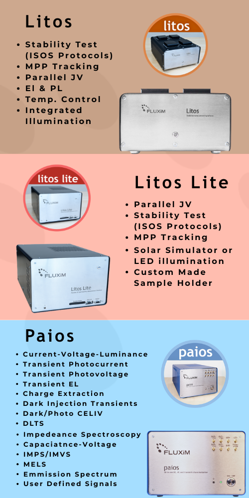
LITOS and LITOS LITE can get the JV characteristics of up to 56 solar cells and keep them at different operating points (MPP, Voc, Jsc) to increase the output of the experiment. With LITOS it is possible to perform accelerated degradation analyses at a maximum light intensity equivalent to 10 suns and under strong UV radiation. LITOS LITE works with a LED solar simulator class AAA, or higher, and can help you performing indoor and outdoor-light experiments.
We designed these instruments with a fundamental idea in mind: solar cells must be characterized and stressed in parallel. On perovskite solar cells the JV characteristics are generally collected at a low scan rate and testing multiple samples in series is time-consuming. Moreover, the different devices on the substate could be too unstable to measure them in series under continuous illumination. We need to control the temperature of the sample, the environment, and the illumination and then collect the curves at the same time if we want to have enough statistics to make solid experimental conclusions.
LITOS can be also coupled to the all-in-one semiconductor parameter analyzer PAIOS. The combined platform automates the sequential stressing and testing of solar cells. The stressing routine can be paused to perform advanced electro-optical characterizations. Different experiments, such as transient measurements (CELIV, TPV, TPC, TEL), impedance spectroscopy, CV, IMPS/IMVS, can be carried out with a single platform without touching the samples. The stressing routine restarts after the analyses and can be paused again to perform the same advanced characterizations at a different degradation point. If we then compare the cell parameters (e.g mobility, trap density, charge density) at different aging periods, we could highlight the mechanisms that are responsible for the degradation of the device. This characterization strategy could also help standardize aging experiments on perovskite solar cells by reducing sources of random errors.
Implement ISOS protocols in your lab
See how Litos Lite supports standardized stability measurements for perovskite solar cells.
-
The ISOS protocols define standardized stress conditions for stability testing:
ISOS-D: Dark storage (no light exposure)
ISOS-L: Constant light soaking
ISOS-O: Outdoor testing under natural sunlight
ISOS-T: Thermal cycling to simulate temperature fluctuations
ISOS-LT: Combined light, temperature, and humidity cycling
-
Comparisons are made by tracking power conversion efficiency (PCE) over time and extracting metrics like T₈₀ (time to 80% of initial or max PCE). Consistent test conditions and parallel measurements across ISOS protocols improve comparability.
-
T₈₀ is widely used, but in cases of “burn-in,” Tmax (time to maximum PCE) followed by a second T₈₀ phase can be more meaningful. Normalized PCE curves and degradation rates also provide critical insight.
-
Accelerated aging applies stressors like elevated temperature, humidity, or light intensity to simulate long-term degradation in shorter periods. The acceleration factor (AF) is calculated using Arrhenius-based models, assuming thermally activated degradation.
-
Light-dark cycling mimics real-world day-night operation. It helps detect reversible degradation (like trap filling or ion migration) and provides insights into how devices recover in the absence of illumination.
-
Yes. Intrinsic factors like light, bias, and heat can be applied in a controlled setup, while extrinsic influences like humidity and oxygen can be introduced via environmental chambers or gloveboxes.
-
Parallel testing enables high-throughput, uniform stress application, and direct comparison across multiple samples. This reduces experimental variability and speeds up material or architecture screening.
-
While Litos Lite does not have built-in temperature or humidity control, it is compatible with external climate chambers, enabling full compliance with ISOS-T and ISOS-LT protocols.
-
Litos Lite records high-resolution PCE over time, enabling precise detection of burn-in regions, followed by Tmax and T₈₀ extraction. This helps distinguish between transient effects and long-term degradation.
-
Yes. Litos Lite allows simultaneous MPPT (Maximum Power Point Tracking) and periodic JV sweeps, supporting hybrid protocols and enabling detailed insight into performance evolution under operational stress.
References
[Sal18] Salibe M. er al. “Measuring Aging Stability of Perovskite Solar Cells“, Joule 2018, 2, 1019-1024
🔗 Looking for a full breakdown of how each ISOS protocol relates to perovskite solar cell degradation?
Read our in-depth guide on ISOS compatibility and perovskite stability →