

Laoss Electrical Module
Optimizing Electrode Design for Large-Area Solar Cells and OLEDs
The Laoss electric module is used to simulate the impact of non-ideal electrodes on the performance of large-area solar cells and OLEDs.
It is possible using Laoss to optimize the electrode geometry in order to minimize at the same time the Ohmic losses and the shadowing effects introduced by the conductive grids. Laoss combines a 2D FEM (Finite Element Model) with a 1D model input by the user describing the current-voltage law of a small device.
Loass helps you answer the following question…
How do you retain the efficiency of a lab-scale optimized solar cell when scaling up to large-area devices?
The electrical module of Laoss is based on a finite element method (FEM). On the two electrodes we solve Ohm’s law in 2D. The electrodes are coupled by a user-defined 1D coupling law (JV curve). Overall this 2+1D approach mimics very well the 3D nature of real applications and is computationally much more efficient than a full 3D treatment. Laoss automatically runs a meshing and solves the partial differential equations for the system.
Dr Ardalan Armin, Ser-SAM group, Department of physics, Swansea University
“We have extensively used both SETOS and LAOSS in our recent endeavour to model large-area OPV and OLED devices. The intuitive workflow of both software packages allows us to quickly try out new ideas before realising them experimentally.”

Case Studies
Reduction of electrical losses
Optimization of the design of the electrodes in OLEDs and PVs. The potential distribution at the top electrode can be optimized by including a metal grid. Suitable for LED lighting panels and large-area solar cells.
Metal finger width optimization
Metal fingers (metal grid) can be added to the transparent electrode of a PV cell in order to improve its conductivity, and as a consequence to improve the device efficiency. In this case, the width of the metal finger has been optimized in order to find the best compromise between two counteracting effects: shadowing due to the metal finger and low conductivity due to the absence of a metal finger.
Choice of the Electrode Material
Two important electrode properties are its transparency and conductivity. Choosing the most efficient material is not an easy task since the relative impact of the conductivity and transparency change with the device size. In this case, is shown how Laoss can be easily used to produce a chart of the best material choice for a PV cell depending on the device size.
Sample 1: Transparency = 85%, σ = 1.14x10^6 S/m
Sample 2: Transparency = 90%, σ = 6.67x10^5 S/m

T R I A L E V A L U A T I O N
TRY Laoss FOR 1 MONTH


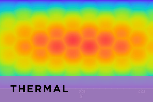
Studying non-ideal Effects in OLEDs and Solar Cells
Electrical shunts are unwanted short-circuits between the two metal electrodes that are drastically degrading the efficiency of the device.
Laoss can simulate the distribution of potential and current in the device when there are electrical shunts. In an OLED these results can be correlated, for example, to the non-uniformity of the device luminescence.
Understanding Electrical Cross-talk in a RGB OLED Pixel Array
Adjacent pixels in OLED displays can be electrically coupled through the lateral leakage current of a common layer. This effect, called cross-talk, results in unwanted light emission from an unaddressed pixel of different colors and reduces the device contrast ratio, and can be detrimental to the color gamut of the device.
With Laoss, we can achieve a quantitative understanding of electrical cross-talk in OLED displays.
Experimental Validation
Laoss simulations have been successfully tested on several experimental results. For example, different experimental results reported in the paper: K. Neyts et al.: “Inhomogeneous luminance in organic light-emitting diodes related to electrode resistivity", have been reproduced.
Here we show the agreement between the experimental and simulated dependence of the luminance on the position along the electrode.
Laoss Videos
Laoss Modules


T R I A L E V A L U A T I O N